Design and fabrication of
fixed roof tanks to API 650!
Design, calculation and fabrication to API 650 · Behineh Ab Engineering
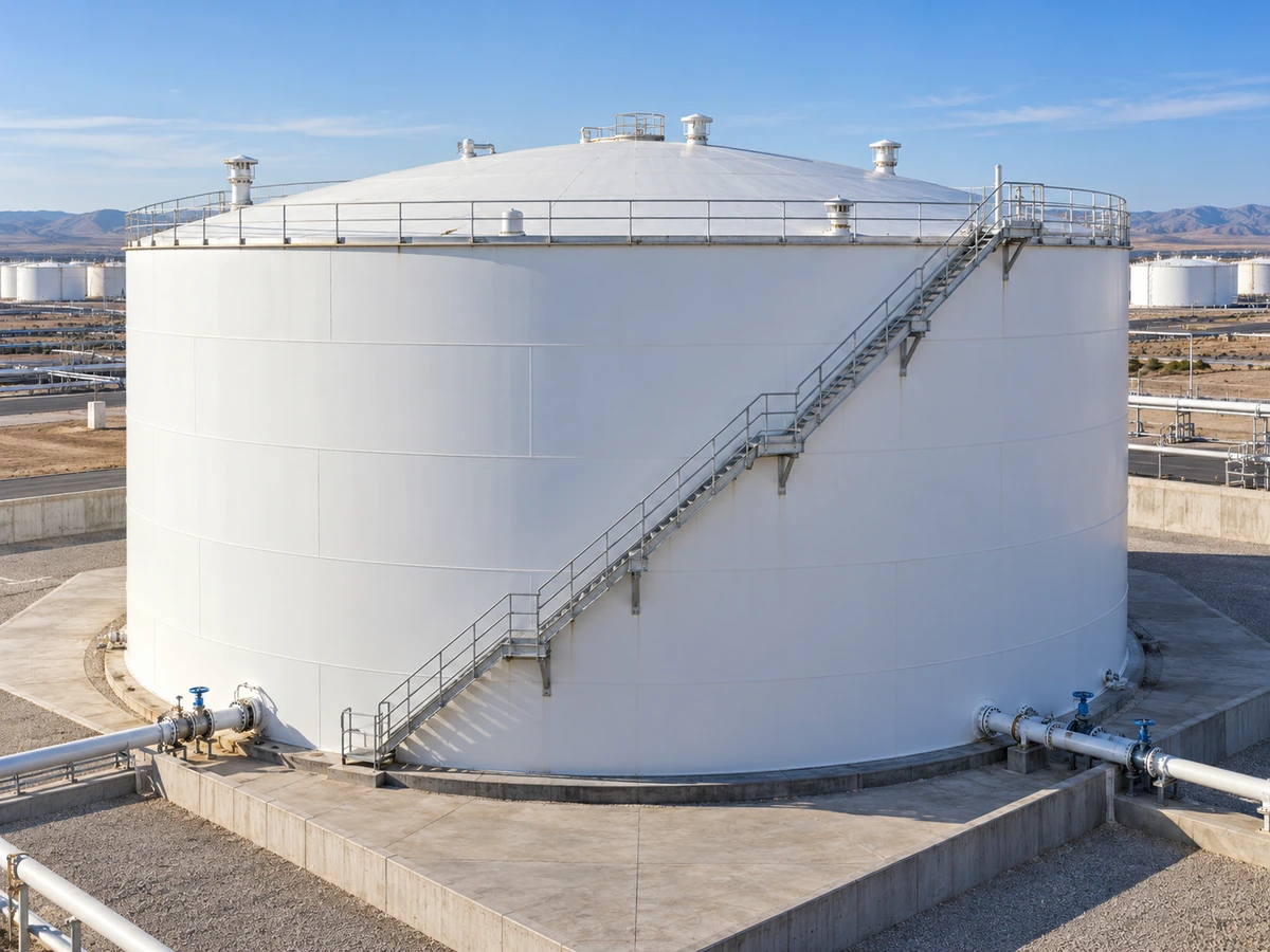
The fixed roof tank is the most common atmospheric tank for storing water, chemicals and petroleum products with a low vapour pressure; the roof is permanently welded to the shell and does not move with the liquid level.
Fixed roof tank
Behineh Ab Engineering — design, calculation and fabrication to API 650
Among atmospheric tanks, the fixed roof tank is the most common type for storing water, chemicals and low-vapour-pressure petroleum products. The roof is permanently attached to the cylindrical shell and, unlike a floating roof, does not rise and fall with the liquid level.
Behineh Ab Engineering wrote this article to explain roof types, applications, breather valves, API 650 requirements, thickness calculation by the variable-design-point method and the fabrication process.
2. Definition and general principles of fixed roof tanks
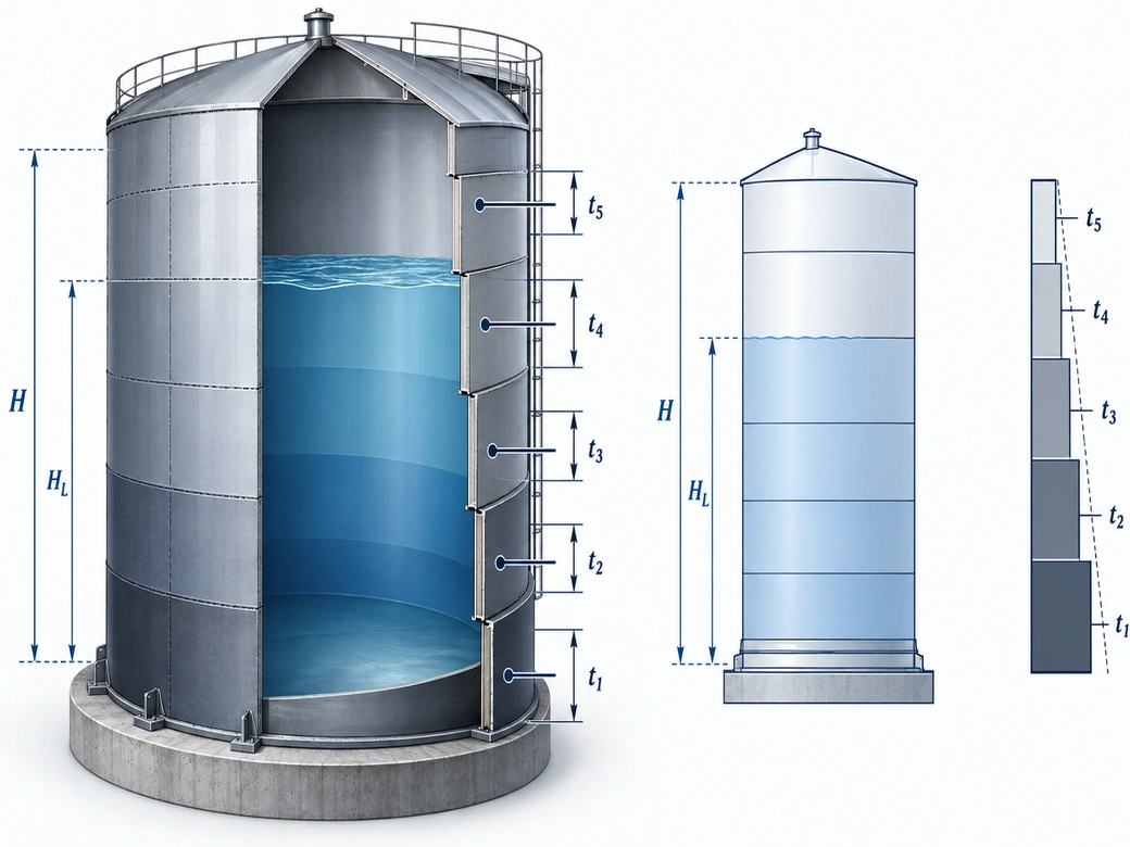
The bottom on the foundation, the shell courses welded with thickness decreasing from bottom to top, and the roof, which keeps out contamination and rain and prevents excessive evaporation. The standard internal design pressure must not exceed the weight of the roof plates and is generally up to about 2.5 psi (≈ 18 kPa); above that, API 620 applies.
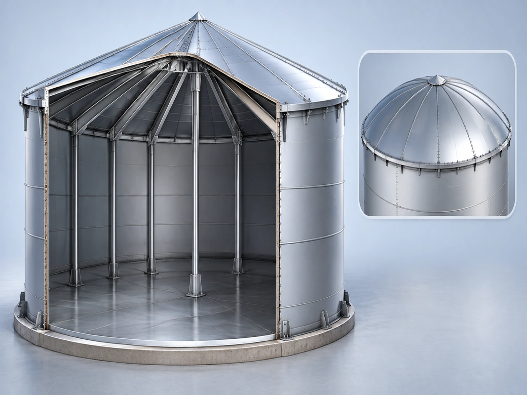
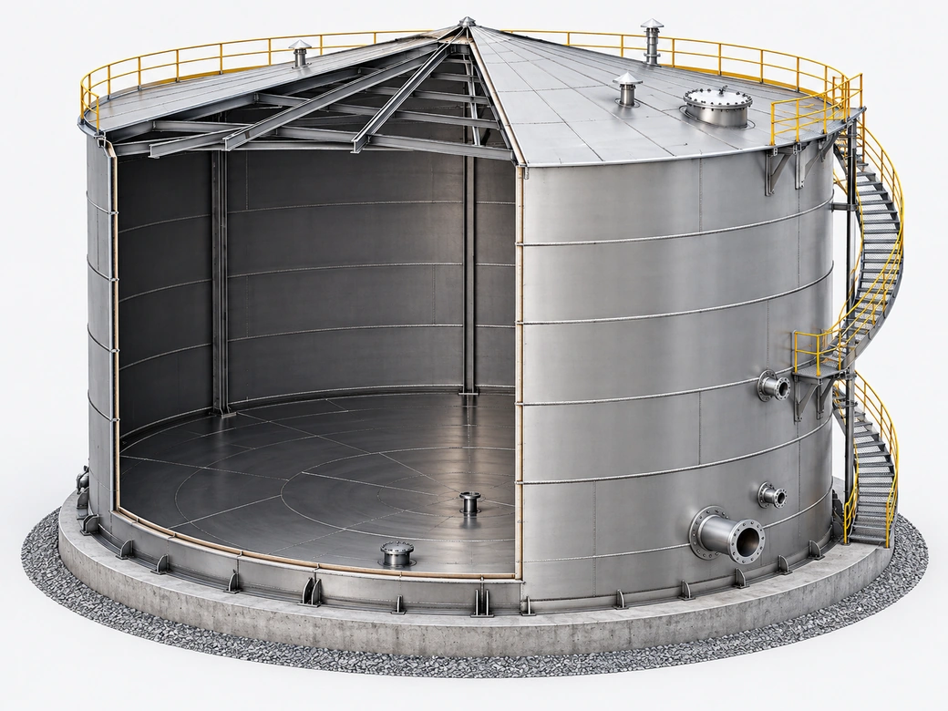
Bottom: sketch plates and thicker annular plates. Shell: the courses. Roof: cone or dome. Top curb / compression ring at the roof-to-shell joint. Appurtenances: manhole, nozzles, stairway, inspection platform, breather valve and drains.
3. Types of fixed roof
The most common type; slope usually 1:16 to 3:4 (1:16 is most economical) for rain drainage. Self-supporting: carried only at its outer edge on the shell, by membrane action; suits small to medium diameters (≈ 18–20 m); fully open inside. Supported: rafters, rings/girders and a centre or internal columns for large diameters.
A dome is part of a sphere; an umbrella roof is made of flat polygonal segments. Usually self-supporting, with load carried mainly in compression in the shell; better pressure/vacuum capacity than a cone. Radius of curvature usually 0.8D to 1.2D. Higher fabrication cost.
| Feature | Self-supporting cone | Column-supported cone | Dome/umbrella |
|---|---|---|---|
| Diameter range | Small to medium | Medium to large | Small to medium |
| Internal structure | None | Columns and trusses | Usually none |
| Relative cost | Low | Medium | High |
| Pressure/vacuum capacity | Low | Low | Higher |
| Open internal space | Full | Limited by columns | Full |
| Roof drainage | Good | Good | Excellent |
4. Applications
Drinking and industrial water, fire water, demineralised and cooling-tower water, and equalisation tanks in wastewater treatment plants.
Fuel oil, diesel, kerosene and lubricating oil. Chemicals and dilute acids/alkalis with suitable material or lining. Food and pharmaceutical solutions in stainless steel. Caustic soda and dilute methanol.
For volatile liquids with a high vapour pressure (gasoline, light crude) a floating roof, or a fixed roof with an internal floating roof, is usually preferred because of evaporation losses and the environment.
5. Breather valve (PV valve)
Liquid movement (filling/emptying). Day/night thermal breathing. Emergency venting during an external fire, with a larger relief capacity.
A disc with weight or spring for positive pressure and vacuum; usually set at a few inches of water column per API 2000. Free vents with insect screens for water. Flame arresters for flammable liquids. N₂ blanketing to prevent oxidation. A blocked or undersized valve is one of the most common causes of tank damage.
6. The API 650 standard
Vertical cylindrical above-ground tanks with a flat or gently coned bottom. Pressure close to atmospheric (up to ≈ 2.5 psi). Typical temperature up to about 93 °C (higher temperatures under special annexes).
| Annex | Subject |
|---|---|
| Annex A | Simplified design of small tanks |
| Annex E | Seismic design |
| Annex F | Small internal pressure |
| Annex M | Elevated temperature |
| Annex V | External vacuum load |
| Annex S/X | Stainless and duplex |
One-foot method: pressure 300 mm above the bottom of each course; up to about 61 m diameter. Variable-design-point: more accurate and economical for large diameters.
7. Shell thickness calculation (VDP method)
Basic SI relations for the design and hydrostatic test thickness of each course; the final result is the larger value, together with the standard minimum:
D diameter (m), H height from the bottom of the course to the top (m), G specific gravity, S_d/S_t allowable design/test stress (MPa), CA corrosion allowance. Nominal shell minimums: D<15 → 5 mm; 15–36 → 6; 36–60 → 8; D≥60 → 10 mm. The one-foot method applies up to about 61 m diameter; VDP is more economical for large-diameter tanks.
7. Details of the variable-design-point method
Check L/H with L = (500·D·t)^0.5. Use the one-foot result for the first course as the starting value. Design-point location x = min(x₁, x₂, x₃) using the parameter C and K = t_L/t_u. Iterate to convergence; then the upper courses, allowing for the effect of the course below. Final choice max(t_d, t_t) plus the standard minimum, rounded up to commercial plate.
8. Other design considerations
Wind, wind girder and anchors where needed. Seismic per Annex E and freeboard. Snow and roof vacuum. Uniform/uneven foundation settlement. Corrosion allowance, internal/external painting and cathodic protection of the bottom.
9. Fabrication process
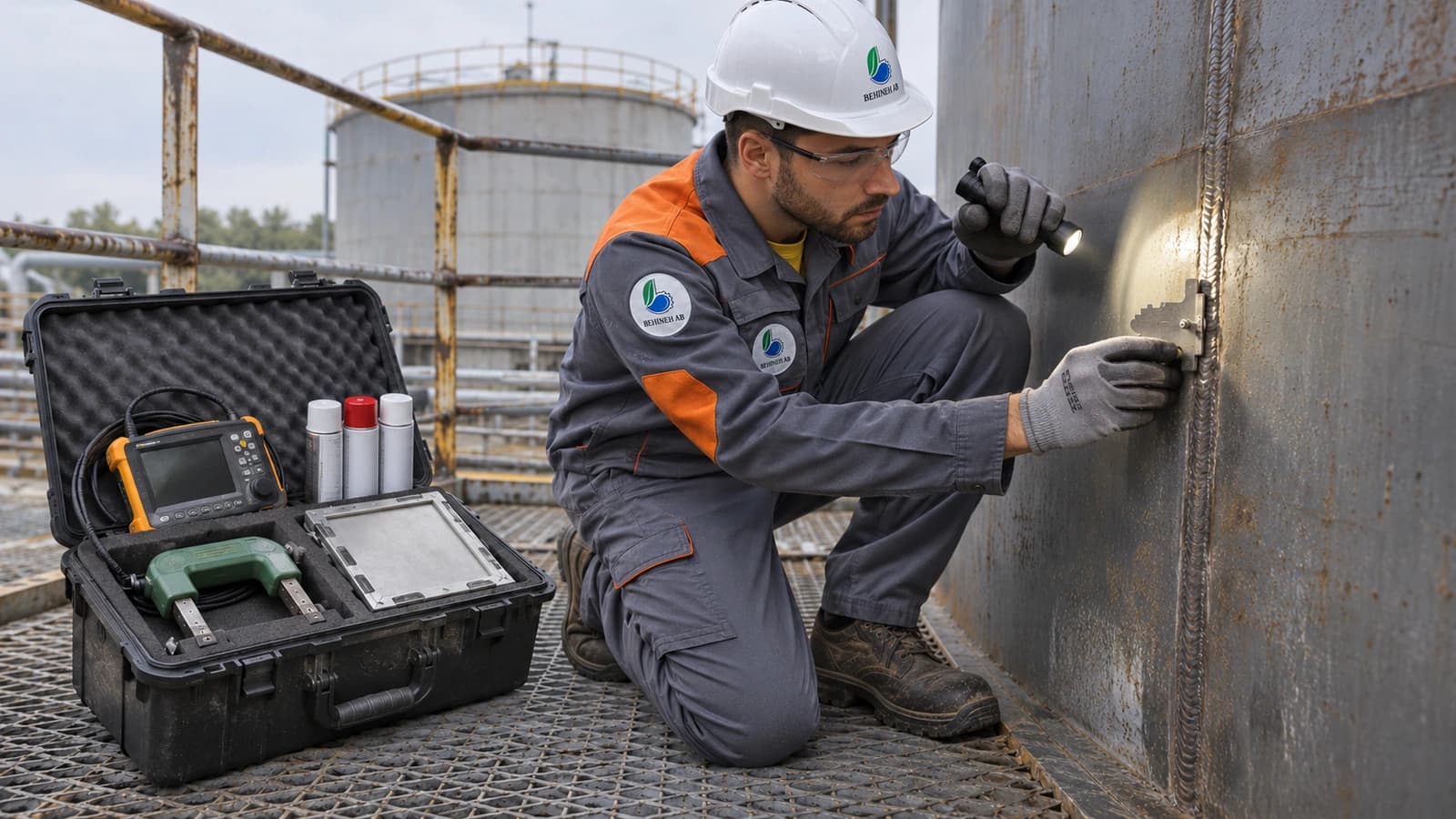
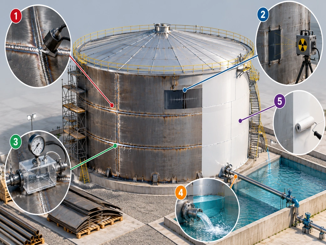
Design and MTO → ring-wall or sand/bitumen bed foundation → cutting, bevelling and rolling → bottom and annular plates → shell erection → roof and compression ring → appurtenances → NDT and hydrostatic test → painting, cathodic protection and handover.
Conventional: from the bottom course upwards with scaffolding. Jack-up: the top course and roof are built at ground level and raised with jacks; safer and faster for large tanks.
| Test | Purpose |
|---|---|
| VT | Appearance of all welds |
| RT | Shell weld seams |
| PT | Surface cracks |
| Vacuum box | Tightness of bottom seams |
| Hydrostatic test | Final structure and tightness |
| Roof box / diesel test | Tightness of roof seams |
Summary
The fixed roof tank is an economical, reliable option for storing water and low-volatility liquids. Choosing the roof type, designing thickness accurately by VDP, fitting the right breather valve, and building and inspecting to API 650 secure long-term life and safety.
Behineh Ab Engineering — design and fabrication of storage tanks and pressure vessels.
Technical specifications
Main components and types of fixed roof
A fixed roof tank has three main parts: the bottom (sketch plates plus thicker annular plates that carry the stress at the bottom-to-shell joint), the shell (several steel courses whose thickness decreases from bottom to top, because hydrostatic pressure is greatest at the bottom) and the roof, which is attached to the top shell course.
Fixed roofs fall into two main groups by geometry and how they carry load: the cone roof, which can be self-supporting or rest on a structure of radial rafters, intermediate rings and one or more internal columns; and the dome or umbrella roof, which suits larger diameters and higher pressure/vacuum capacity but costs more to build.
Breather valves and vent safety equipment
Because the roof is fixed and does not move with the liquid level, changes in liquid volume or temperature make the vapour space above the liquid expand or contract. If that space cannot 'breathe', the tank bursts from overpressure or implodes from internal vacuum; the pressure/vacuum relief valve restores the pressure balance automatically.
Three main factors create the need to breathe: liquid movement (filling or emptying the tank), thermal breathing (vapour expanding and contracting with daily heating and cooling), and emergencies such as an external fire that sharply increases the evaporation rate. Other related equipment includes free vents, flame arresters (for flammable fluids) and inert-gas (N₂) blanketing to keep a neutral gas layer over the liquid.
When is a fixed roof not suitable?
For volatile liquids with a high vapour pressure, such as gasoline and light crude oil, significant evaporation losses and environmental concerns usually call for floating roof tanks or a fixed roof tank fitted with an internal floating roof. A plain fixed roof is not an economical option in these uses.
API 650 and its key annexes
API 650 (Welded Tanks for Oil Storage) is the main international reference for the design, fabrication, inspection and testing of welded atmospheric steel storage tanks, covering requirements for the bottom, shell, roof, connections, materials and welding. It applies to vertical cylindrical above-ground tanks with a design pressure close to atmospheric (up to about 2.5 psi for a standard fixed roof) and a design temperature usually up to about 93 °C.
Shell thickness by the variable-design-point (VDP) method
API 650 gives two main methods for setting shell-course thickness: the one-foot method, which calculates each course's thickness from the hydrostatic pressure at a point 300 mm (1 ft) above the bottom of that course and is limited to tanks up to about 61 m in diameter; and the variable-design-point method, which is more accurate, gives a thinner and more economical shell, and is recommended for large-diameter tanks.
The method is permitted when L/H ≤ 1000/6. The design thickness and hydrostatic test thickness of each course are found from the relations below.
API 650 — VDP applicability condition
API 650 — design thickness (VDP)
API 650 — hydrostatic test thickness
- t_d ≈ 8.7 mm
Symbols
- LCharacteristic length for checking the L/H condition (mm)
- DNominal tank diameter (m)
- tThickness of the course being checked (mm)
- HDesign liquid height from the bottom of the course to the design level (m)
- t_dDesign thickness of the course (mm)
- t_tHydrostatic test thickness of the course (mm)
- GSpecific gravity of the stored liquid relative to water
- S_dAllowable design stress of the steel (MPa)
- S_tAllowable hydrostatic test stress (MPa)
- CACorrosion allowance (mm)
For example, for a water tank with D = 20 m, H = 12 m, G = 1, S_d = 160 MPa and CA = 1.5 mm, the design thickness of the bottom course comes to about 8.7 mm, rounded up to commercial plate of about 9 to 10 mm; on larger tanks the VDP method optimises this value compared with the one-foot method.
Minimum shell thickness and the fabrication process
Whatever the calculation gives, no course may be thinner than the standard minimums (including corrosion allowance): 5 mm for diameters under 15 m, 6 mm for 15 to 36 m, 8 mm for 36 to 60 m and 10 mm for 60 m and above.
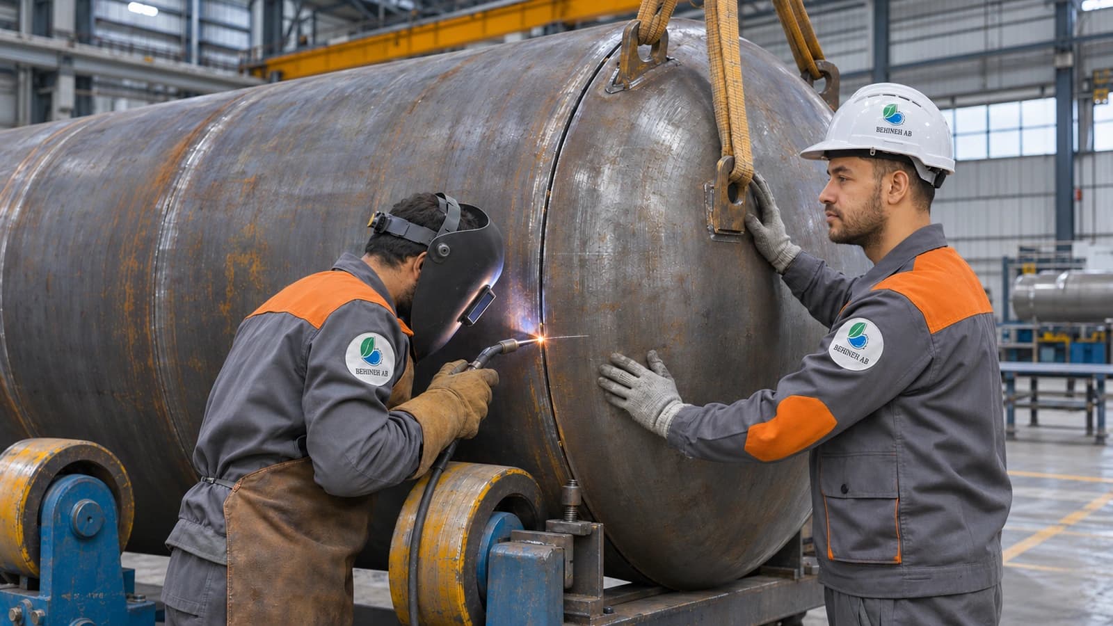
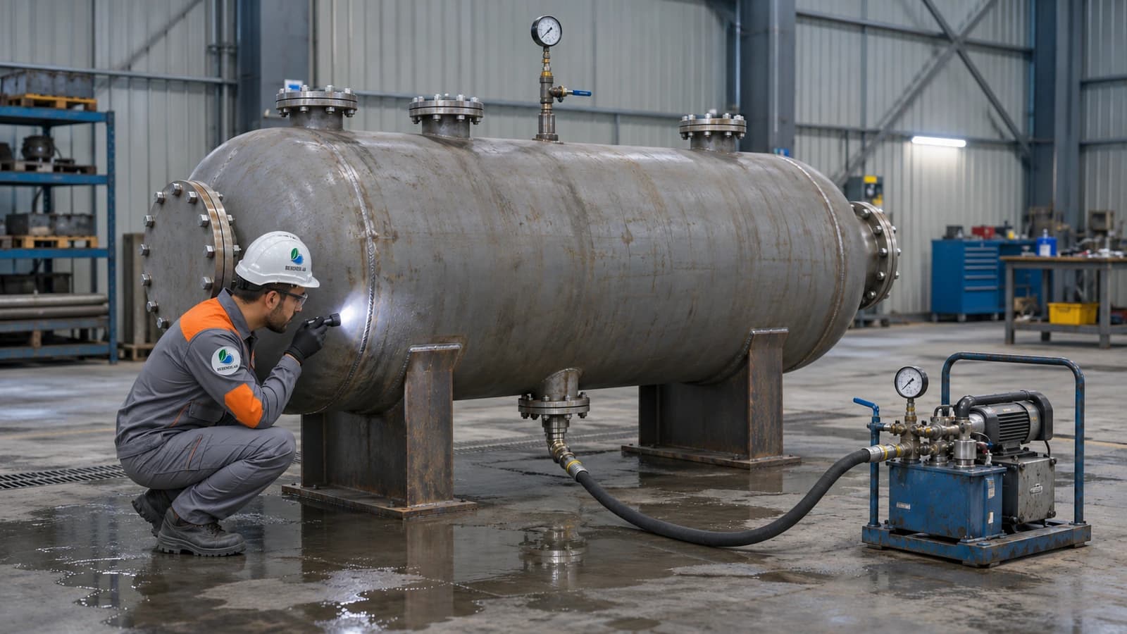
Building a fixed roof tank is a chain of steps: design and drawings with a material take-off, foundation preparation, cutting and bevelling the plates, laying the bottom and annular plates, erecting the shell (course by course or by jack-up), installing the roof and accessories, and finally inspection, non-destructive testing and the hydrostatic test before painting and final handover.
Applications and industries
Photo gallery
Fixed roof tank gallery
Frequently asked questions
Request a quote
Fixed roof tank
Enter the pressure, temperature and fluid; our engineers send a technical proposal and price within 24 working hours.
- Written technical reply with a proposed concept drawing
- Site visit in Tehran and surroundings
- 24-month warranty on fabrication and welding