Design and fabrication of
mazut tanks for power plants and industry!
An engineering, fabrication and inspection guide to power-plant mazut storage tanks
Heavy mazut is practically unpumpable at ambient temperature; the tank must usually keep the bulk fluid at 50 to 70 °C so its viscosity suits positive-displacement pumps.
Building storage tanks for
power-plant mazut · Behineh Ab Engineering
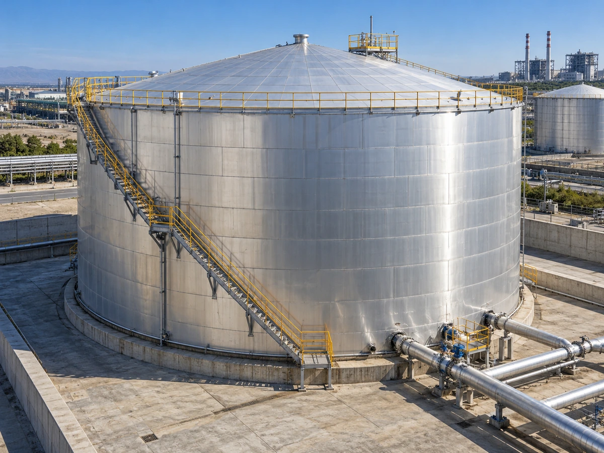
Mazut (heavy fuel oil / residual fuel oil) is the residue of distillation and cracking: a mixture of heavy hydrocarbons, asphaltenes, resins and sulphur compounds. The viscosity of grades such as IFO-380 at 50 °C can reach 380 cSt or more, and at ambient temperature it is practically unpumpable. The pour point of many grades is 24–36 °C.
That is why a mazut tank is not just a structure; it needs an integrated heating system, insulation and instrumentation. Applications: thermal power plants (winter peak and gas restrictions), cement kilns and port bunkering. This article covers the path from API 650 and seismic design to coils, insulation, site fabrication, instrumentation, final inspection and HSE.
2. Mechanical design standards
| Parameter | API 650 | ASME VIII |
|---|---|---|
| Pressure | Near atmospheric · up to ≈18 kPa | Higher pressure · day tank / exchanger |
| Mazut use | Main storage 5,000 to 50,000+ m³ | Pressurised auxiliary parts |
| Thickness calculation | Hydrostatic column · shell-controlled | Membrane stress from internal pressure |
Appendix E: base shear and overturning from impulsive mass and sloshing; base buckling and uplift restraint. Appendix V: overturning when full and shell buckling when empty → wind girder. Snow, maintenance live load, breather vacuum/pressure and the dead weight of ladders and insulation in the roof and shell load combinations.
3. Heating systems
Thermal oil at 180–250 °C in a closed loop — smaller exchange area but more pump/expansion complexity. Steam at 6–10 bar (160–180 °C) is common in power plants; lines to ASME B31.1/B31.3 with steam traps and slopes to prevent water hammer. Coils on cradles 150–200 mm above the bottom so they are not buried in sludge.
A small exchanger at the outlet nozzle or suction sump for cold starts and low levels. Heat flux is limited to prevent coking on the tube.
Weld the hardest-to-reach joints first; expansion loops / sliding supports; GTAW root + SMAW fill; hydrotest at 1.5× design (B31.3) + PT/pneumatic. Several independent circuits with isolation valves so repairs can be made without emptying the tank.
2.2. Shell thickness API 650
For tanks under 61 m in diameter, the one-foot method is usually used:
Mazut's higher density compared with light products increases the thickness of the lower courses and the seismic forces (impulsive/convective mass); anchor bolts and anchor chairs are often needed to prevent uplift. Wind load (Appendix V) must include the weight of insulation and cladding in the wind area. Pressure parts (exchangers, coil heaters, pressurised day tanks) usually follow ASME VIII.
4. Thermal insulation
λ ≈ 0.035–0.045 W/m·K, density 100–150 kg/m³, class A1. Thickness from allowable heat loss and a cladding surface temperature <60–65 °C. Cold/windy climates 100–150 mm; hot port sites 50–80 mm with stronger sealing. Al 3003 cladding 0.5–0.8 mm, overlapped top over bottom, with stainless bands — to prevent CUI.
5. Site fabrication and assembly
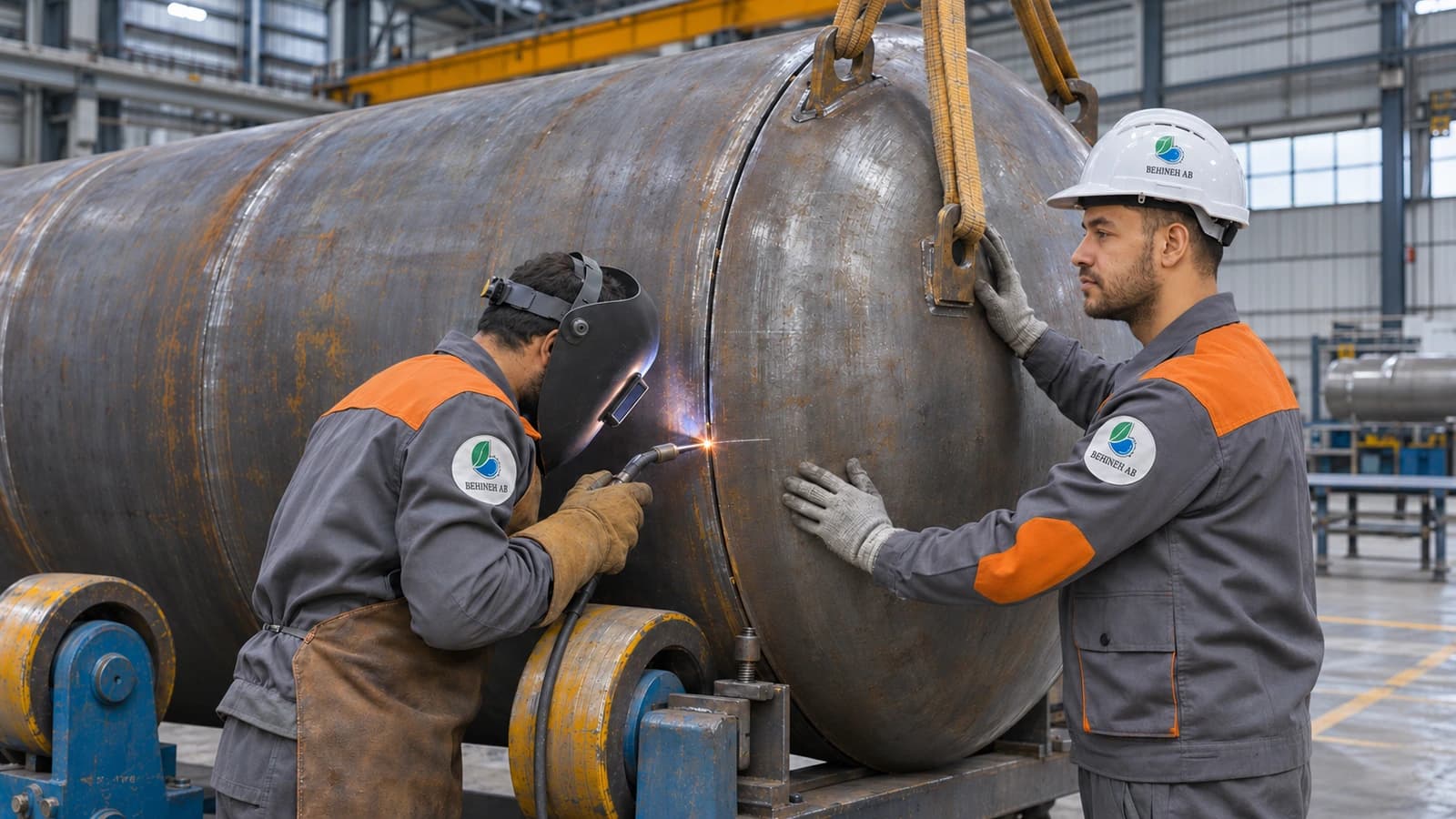
Ring wall + sand bed or sand-asphalt bed; drainage and sometimes cathodic protection of the bottom. Thicker annular plates + sketch plates, lapped or butt-welded. Shell rolling; bottom-up or jacking erection. SMAW root, SAW main seams with an anti-distortion sequence.
6. Instrumentation
GWR or FMCW radar with probes rated to ≈150 °C (PTFE coated), stilling well, kept clear of the coil. Multi-point RTD/TC to control heating and avoid cold spots. Steam/oil network pressure, a back-up float, and leak detection under the bottom.
7. Final technical inspection
| Method | Main use |
|---|---|
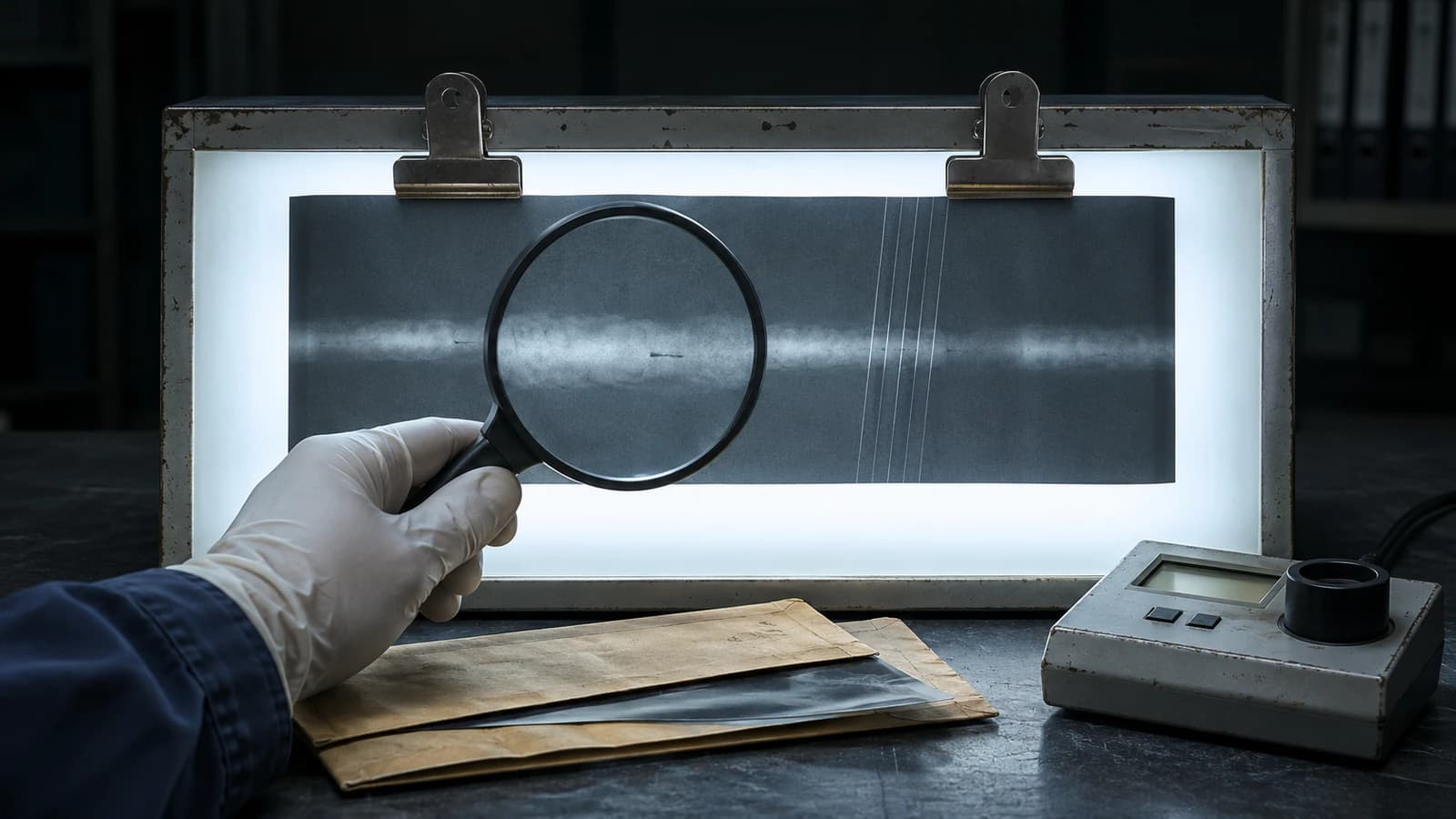
| RT | Vertical/circumferential shell seams · spot or full |
| UT | Baseline thickness and welds where RT access is limited |
| PT | Nozzle, coil and roof fillets |
| Vacuum box | All bottom seams · vacuum ≥≈21 kPa |
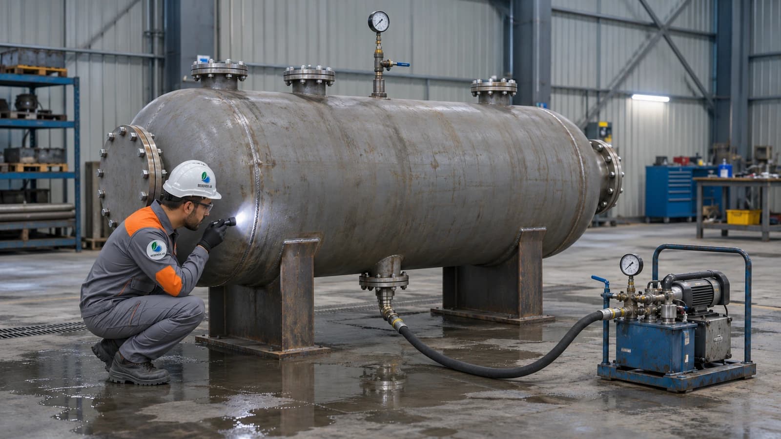
| Shell hydrotest | Staged filling + settlement monitoring |
| Roof | Low-pressure air + foaming agent · breather |
8. HSE considerations
Bund of at least 110% of the largest tank with an impermeable lining; spacing per NFPA 30. Foam chamber + cooling spray + bund foam ring. Grounding/lightning protection and hazardous area classification.
9. Corrosion and maintenance
Pitting of the bottom and lower shell from sulphur compounds and free water. Epoxy-phenolic coating, cathodic protection of the bottom, periodic draining of water and sludge, and in-service/out-of-service inspection under API 653.
Summary
A reliable mazut tank results from an API 650 structure, the right heating and insulation, accurate welding and NDT, and preventive maintenance against sulphur corrosion.
Behineh Ab Engineering designs, builds and delivers mazut tanks for power plants and industry to suit the site's capacity, climate and heat source.
Technical specifications
Why is a suction heater needed?
During a cold start or at low level, heating the whole bulk is not enough; the suction heater quickly heats just the suction zone so the pump can draw flow without coking on the tube.
Why several coil circuits?
With separate isolation valves, a leaking circuit can be repaired without emptying the whole tank — a practical requirement for continuous power-plant operation.
What is the CUI risk?
Moisture getting under the cladding causes corrosion under insulation (CUI) on the shell, which cannot be seen from outside; correct overlaps and stainless bands are vital.
Applications and industries
Photo gallery
Storage tank gallery
Frequently asked questions
Request a quote
Mazut (HFO) tank fabrication
Enter the pressure, temperature and fluid; our engineers send a technical proposal and price within 24 working hours.
- Written technical reply with a proposed concept drawing
- Site visit in Tehran and surroundings
- 24-month warranty on fabrication and welding