Design and fabrication of
industrial dust cyclones!
A step-by-step guide to design, calculation and shop fabrication
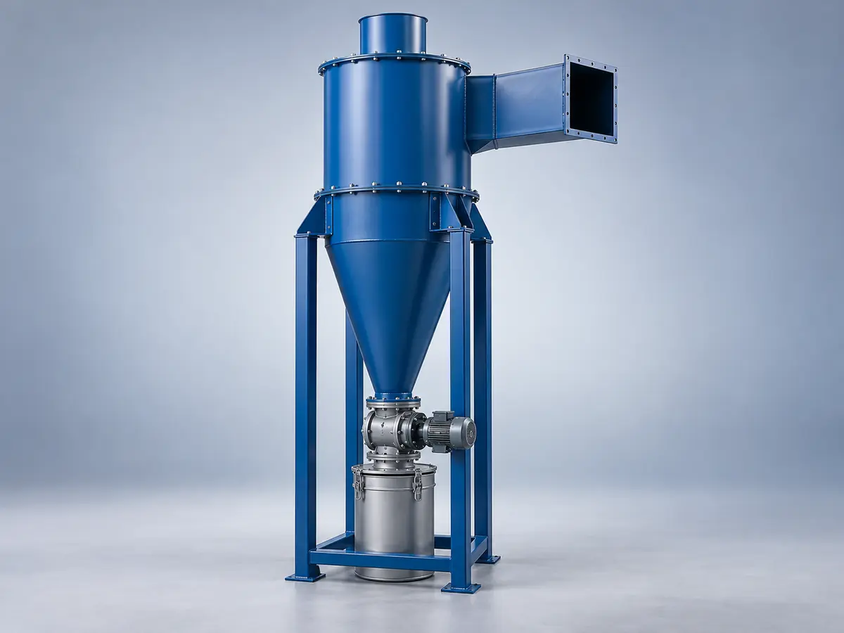
A cyclone separates solid particles from gas by centrifugal force, with no moving parts or consumable filter. The outer vortex drives the particles to the wall and into the hopper, and the clean gas leaves through the vortex finder.
1. Introduction — the cyclone
Particle separation by centrifugal force
A cyclone separator is simple mechanical equipment that separates suspended solid particles from a gas stream by centrifugal force, with no moving parts or consumable filter. The gas-particle mixture enters a cylindrical-conical chamber tangentially; because of their higher inertia the particles are driven to the wall and fall into the hopper, while the lighter gas leaves through the vortex finder.
Because of its simple structure, low fabrication and maintenance cost, resistance to high temperature and humidity, and no need for direct electrical power (apart from the suction fan), it is widely used in cement, wood and MDF, flour and grain, mining and industrial dust collection systems as a pre-cleaner before a bag filter or electrostatic precipitator.
2. Operating principles and physics
Tangential or involute entry through a rectangular duct turns the linear velocity into a descending spin (the outer vortex). The centrifugal acceleration can be tens to hundreds of times g.
At the end of the cone the flow reverses direction, and the central rising vortex (the inner vortex) leaves through the vortex finder, usually to the suction fan or the next cleaning stage.
The particles lose velocity at the wall and slide into the hopper by gravity; discharge is usually through a rotary valve or flap/dust valve without breaking the vacuum.
3. Steps of dimensional and hydraulic design
The dimensions are defined relative to the body diameter D.
| Dimension (relative to D) | Lapple (general) | High-efficiency note |
|---|---|---|
| Inlet height a | 0.5D | Taller; more pressure drop |
| Inlet width b | 0.25D | Often a narrower inlet |
| Vortex finder diameter Dₑ | 0.5D | Usually smaller |
| Cylinder height h | 2D | Larger H/D ratio |
| Overall height H | 4D | Swift / Stairmand HE |
| Hopper opening B | 0.25D | — |
| Vortex finder length S | 0.625D | Sensitive to efficiency and ΔP |
Conventional (Lapple) versus high-efficiency (Swift/Stairmand) design: efficiency on finer particles in return for higher Nₕ and fan power. Multi-variable optimisation between the desired efficiency and an economic pressure drop is essential.
3.2–3.3. Key performance relations
The cut diameter d50 and the pressure drop in terms of the inlet velocity head are the two main indicators of hydraulic design:
μ is the gas viscosity, b the inlet width, Nₑ the number of effective turns (usually 5 to 10), Vᵢ the inlet velocity, ρₚ and ρ_g the particle and gas densities. After d50, the fractional efficiency is found from the grade efficiency curve (Lapple / Barth / Iozia-Leith) and the overall efficiency by weighting over the particle size distribution.
4. Mechanical design and materials engineering
Unlike pressure vessels, in a cyclone wear (erosion) is usually the main factor in plate thickness.
The inlet area, the wall opposite the inlet and the whole cone take the most impact. The initial thickness must be chosen above the structural minimum with an erosion allowance so that the service life is achieved.
Carbon steel (ST37/A36) for low dust loads. Hardox 400/450/500 for severe wear (cement, mining, silica) with a hardness of about 400–500 HB. Alumina ceramic tiles for very high wear/temperature, with local replacement possible. Elastomer or polyurethane for low temperature and softer particles. The final choice is based on life cycle cost.
5. Shop fabrication process
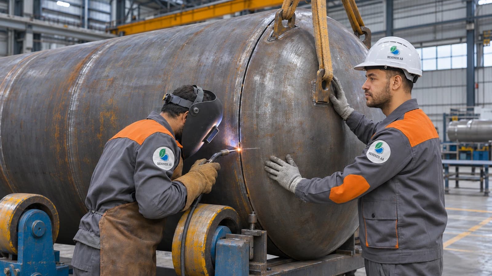
Three- or four-roll rolling with springback control, edge alignment before the longitudinal seam to prevent ovality, and, for large diameters, welding of segments.
A mathematically accurate flat pattern (large/small radius and slant height), usually cut by CNC plasma or laser. Rolling with a varying radius or cone rolling, checked with a template. The joint to the cylinder with a circumferential tolerance usually under 2–3 mm and concentricity checked with a laser plumb; misalignment ruins the symmetry of the vortex and the efficiency.
Simple tangential: easier to build, more turbulence and ΔP at the joint. Involute/scroll: gradual guidance, better efficiency and lower pressure drop; increasingly preferred in cement and mining. Burr-free internal welds and square duct walls are essential.
A cyclone works under negative pressure; false air from a fine crack ruins the efficiency and fan consumption. Full continuous welds, a controlled welding sequence to reduce distortion, and grinding of the internal flow-path surface.
Flange flatness for sealing without field correction. A hopper angle greater than the material's angle of repose so that bridging does not occur. A fully sealed connection to the rotary/double flap valve so that unwanted air from below does not re-entrain the particles.
6. Shop drawings, assembly and installation
General assembly with the hydraulic dimensions, flat patterns of the cylinder/cone/inlet, weld details with the type and sequence of welds, and the foundation/support structure drawing with the load of the unit full of material in the worst case.
Cylinder levelled on a fixture → concentric cone → vortex finder at the exact length S → inlet → hopper and discharge valve. On site, verticality and support strength are documented with a laser level.
7. Extending service life against wear
Hardox plate or ceramic at the inlet, the opposite wall and the cone; replacing the liner instead of the whole body lowers repair costs.
Chromium-carbide weld deposits on critical areas as an economical alternative to a separate liner.
A larger radius of curvature on the involute inlet reduces direct impact. Periodic ultrasonic thickness measurement at critical points for preventive repair before the wall wears through.
8. Shop quality control
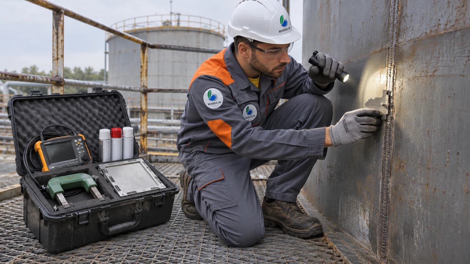
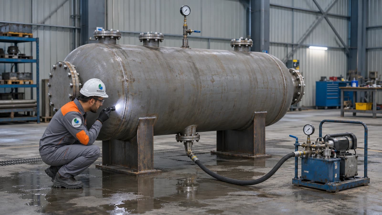
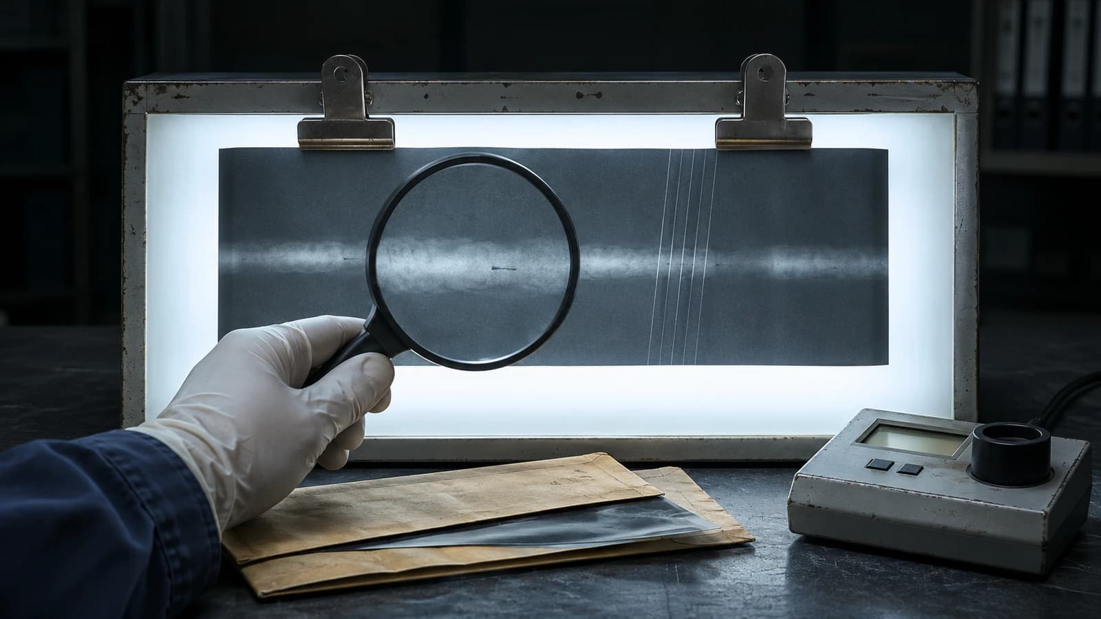
Air soap bubble test at a controlled internal pressure. Vacuum box for particular seams. DPT for surface cracks on flanges and highly stressed areas.
Cylinder ovality measured with a circumference tape, concentricity of the cone and cylinder, depth and concentricity of the vortex finder, and inlet dimensions and angle. Any deviation from tolerance directly reduces the design efficiency.
Dynamic balancing of the rotor (for example ISO 21940), control of rotor clearance to prevent air leakage and contact wear, a no-load run test, and sealing of the hopper-to-valve flange.
9. Conclusion
Because of its simplicity, the absence of moving parts in the separation path, its low cost compared with a bag filter or electrostatic precipitator, and its ability to work at high temperature, the cyclone remains a widely used pre-cleaner and separator in cement, mining, wood, flour and dust collection. A successful design needs a balance between geometry (Lapple versus Swift), efficiency and ΔP, wear-resistant material, and precise rolling and welding, especially of the cone.
Its inherent challenges are constant wear of the body and a sharp drop in efficiency for particles usually below 10 μm. Under strict emission standards, a cyclone is usually an economical pre-cleaner before secondary treatment (a bag filter), not the final solution.
Technical specifications
When is a cyclone chosen instead of a bag filter?
A cyclone is economical for coarser particles and high dust loads and has no media maintenance cost. For very fine particles it is usually used as a pre-separator before a bag filter or electrostatic precipitator.
Parameters that affect cyclone efficiency
Inlet size, gas velocity, body diameter, cone angle and particle density are the most important factors. Higher velocity raises efficiency but also increases pressure drop and wear, so a balanced design is essential.
Applications and industries
Photo gallery
Cyclone gallery
Frequently asked questions
Request a quote
Cyclone
Enter the pressure, temperature and fluid; our engineers send a technical proposal and price within 24 working hours.
- Written technical reply with a proposed concept drawing
- Site visit in Tehran and surroundings
- 24-month warranty on fabrication and welding