Crown radius 1.3 times the vessel's inside diameter

Diffuser head (Diffuser)

A deeper dome for flow and fluid distribution requirements at the vessel inlet/outlet

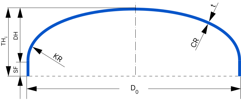
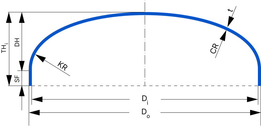
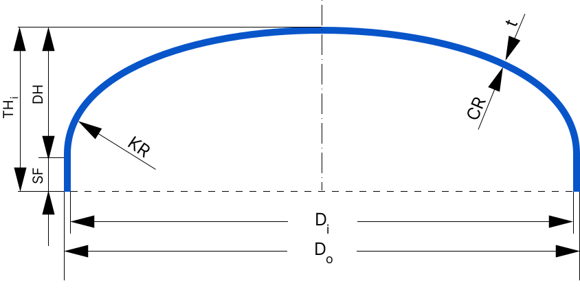
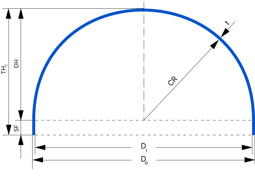
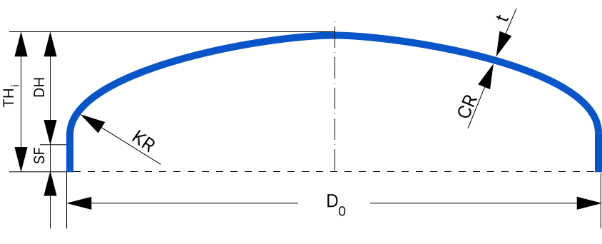
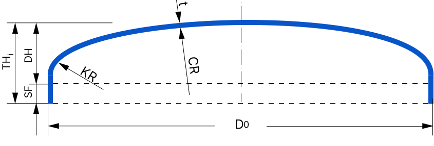
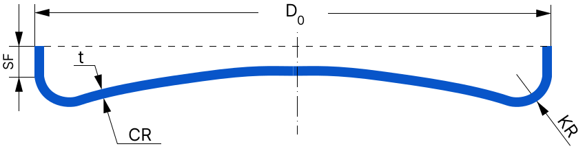
In its basic formula the diffuser head is like a standard dished head (KR in the 15 to 50 millimetre range, SF at least 3.5 times the thickness), but its crown radius (CR) is taken as 1.3×Di instead of being equal to the inside diameter; that is, a flatter dome that is at the same time deeper in the knuckle area than a standard dished head.
Diffuser head

Diffuser head

  • CR = 1.3 × Di
  • KR = 15–50 mm (acc. Di)
  • SF ≥ 3.5 × t
  • DH 168 mm
  • THi 210 mm
  • KR 42 mm
  • CR 1820 mm
  • SF 42 mm
CR formula
CR = 1.3 × Di
KR range
15 to 50 millimetres (based on diameter)
SF formula
Greater of 3.5×t or 0.03×Di
Main use
Inlet/outlet points that need even flow distribution
Dome radius 1.3 times the inside diameter
Deeper at the knuckle than standard dished
Suited to even flow distribution
KR range similar to standard dished
A process application, not just a structural one
Made in carbon steel and stainless

What is a diffuser head?

In its basic formula, a diffuser head is like a standard dished head, but its dome radius is taken as 1.3×Di instead of being equal to the inside diameter; that is, a dome with a different geometry for spreading flow.

This type is usually chosen where even distribution of the incoming or outgoing fluid matters, not just closing the end of the vessel; the name "diffuser" comes from this role.

Geometry formulas of the diffuser head

The main difference from standard dished is only in the dome radius coefficient:

Dome radius
CR = 1.3 × Di
Knuckle radius
KR = 15–50 mm
Straight flange
SF ≥ max(3.5 t, 0.03 Di)
Use
Flow inlet / outlet
Workshop note

In some applications the head also shapes the path by which fluid enters or leaves. A suitable dome radius can prevent excessive turbulence near the nozzle.

Online calculation

See the head's dimensions, volume and weight for a real diameter and thickness

Diffuser head (Diffuser)

Diffuser head

Diffuser head

  • CR = 1.3 × Di
  • KR = 15–50 mm (acc. Di)
  • SF ≥ 3.5 × t
  • DH 168 mm
  • THi 210 mm
  • KR 42 mm
  • CR 1820 mm
  • SF 42 mm

Liquid level and volume inside this head

How the head is mounted
Internal surface area of the head0m²
Plate weight of this head0kg
Liquid weight at this level0kg
Full capacity of this head0m³
Liquid volume in this head0m³
Total weight (fluid + head)0kg

Development of this head (flat blank before forming)

The diameter of a flat plate of the same thickness and material that weighs the same as the formed head — an initial workshop estimate based on equal weight, not allowing for thickening or extra stretching at the knuckle.

Flat blank radius (development)0mm
Flat blank diameter (development)0mm
Flat blank area0m²

The vessel head production process

From calculating the blank diameter to final edge preparation — the steps of making a vessel head in the workshop

  1. Calculating the blank diameter

    Cutting a disc from plate with the diameter and thickness calculated for the head type and vessel diameter

  2. Cutting the plate blank

    Precise cutting of steel or stainless plate by plasma, laser or gas according to the technical drawing

  3. Pressing the head

    Hot or cold forming of the disc with a die and industrial press until it reaches the final head profile

  4. Edge preparation

    Machining the edge, bevelling and preparing the weld area for fitting to the vessel shell
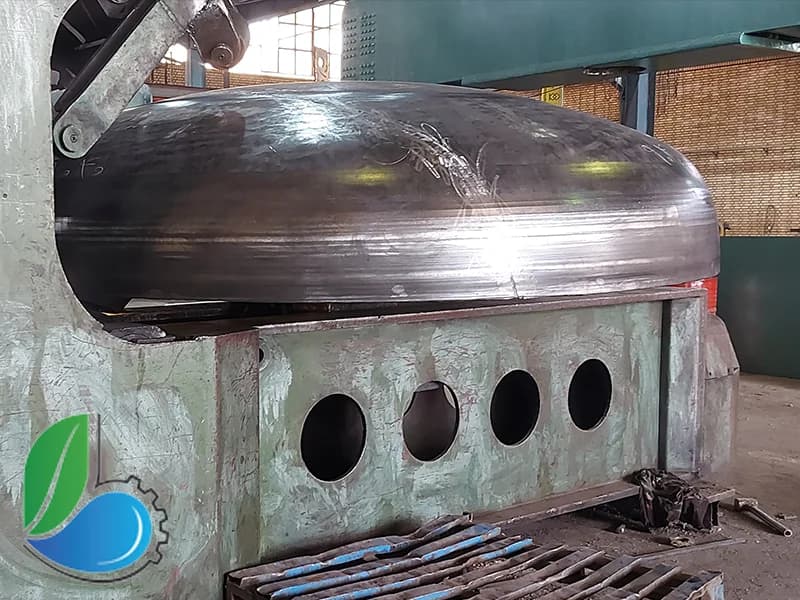
Pressing a vessel head in the Behineh Ab workshopVideo coming soon

Choosing a head: the balance between pressure, cost and time

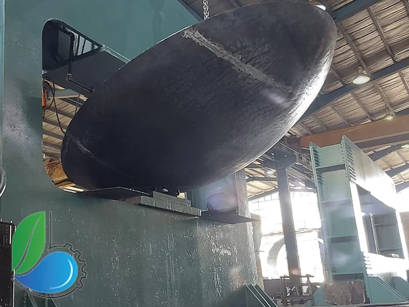
In some applications the head is not just a structural cover but also shapes the path by which fluid enters or leaves. Choosing a suitable crown radius can prevent excessive turbulence or uneven flow distribution near the inlet nozzle; the diffuser head is designed for exactly this purpose.
1Take the design pressure and temperature from the data sheet
2Check the height limit at the installation site
3Compare the cost of plate with the cost of pressing
4Consider die availability and delivery time
Pressed heads in the workshop store

Applications and industries served

Inlets/outlets of process vessels with sensitive flow
Chemical reactors that need even fluid distribution
Mixing tanks with inlet flow control
Petrochemical process equipment

Buying heads from Behineh Ab

Six steps from first contact to delivery

1Send the head specifications

Give the outside diameter, plate thickness, head type and required material.

2Technical quotation

The calculated weight, unit price and delivery time are sent the same business day.

3Plate supply

Plate is supplied with the mill certificate and inspected on arrival before cutting.

4Cutting and pressing

Cutting the disc, hot or cold pressing depending on thickness, and checking dimensions with a template.

5Edge machining and bevelling

Machining the cylindrical edge and bevelling it ready for welding to the shell.

6Packing and shipping

Packing, issuing the part identification sheet and shipping nationwide.

What sets us apart

Ready dies for the most common diameters
Thickness checked after pressing with a thickness gauge
Profile checked against a reference template for each form
Plate material certificate with every shipment
Hot pressing for thicknesses above 16 mm
Stainless and galvanized heads available

Price inquiry
vessel head

Enter the diameter, thickness and head type; you will receive the calculated weight and unit price.

  • Quotation with the exact weight of the part
  • Standard heads delivered in 7 business days
  • Shipping nationwide
Direct line to engineering office
021 - 3345 6789

Your information is confidential and used only to prepare a technical proposal.

Other head types

All articles
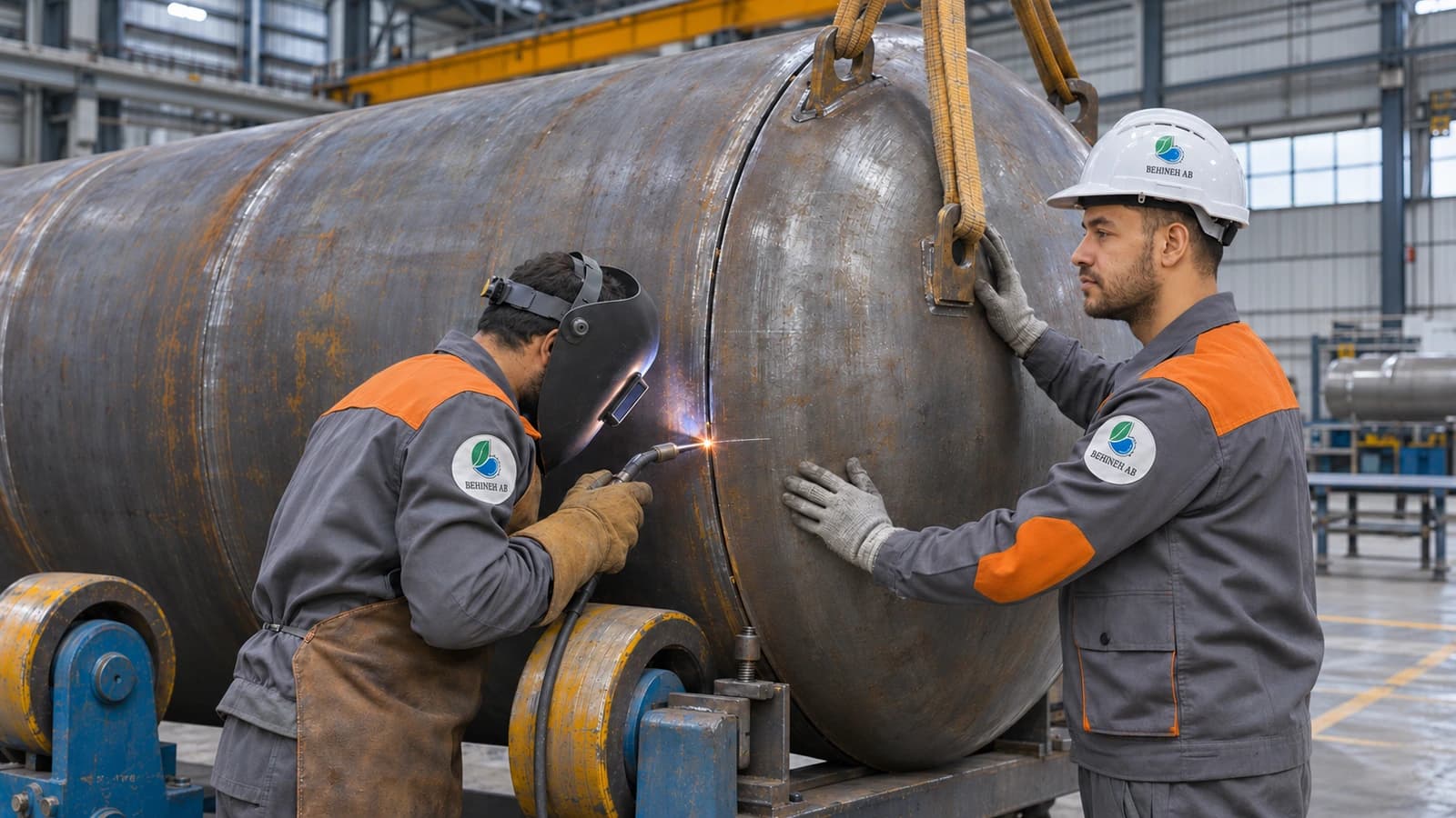
  • Assembling the shell and head of a steel tank in the Behineh Ab tank fabrication workshop

    Steel Tank Manufacturing Steps, from Order to Delivery

    The steps of building a steel tank, from the data sheet to testing and dispatch. A 20,000-litre tank takes about three weeks; here is what that time is spent on.

    Read more
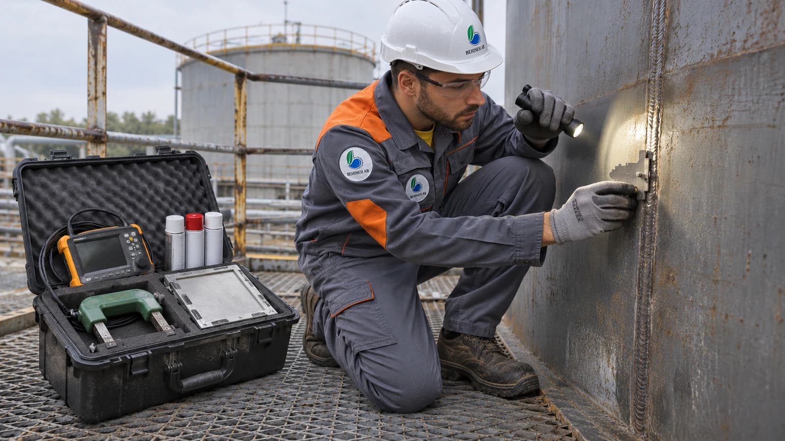
  • Inspector carrying out a non-destructive test on a steel tank shell weld

    Tank Tests: What Defect Does Each Test Find?

    Hydrotest, radiography, ultrasonic, liquid penetrant, magnetic particle and vacuum box. Each finds a particular defect and none can replace another. Here we compare them.

    Read more
  • Pressure vessel under hydrostatic test with a pressure gauge in the Behineh Ab workshop

    Tank Hydrostatic Test, Step by Step

    The hydrotest is a tank's final exam before delivery, and we carry it out in our own factory. The test pressure, the work before filling, and the mistake that can ruin a tank while it is being drained.

    Read more
  • Radiography film of a tank shell weld on a film viewer

    Weld Radiography: What Percentage of Seams Must Be Tested?

    The radiography percentage sets the joint efficiency, and the joint efficiency sets the plate thickness. In other words, this decision directly affects the tank's weight and price.

    Read more