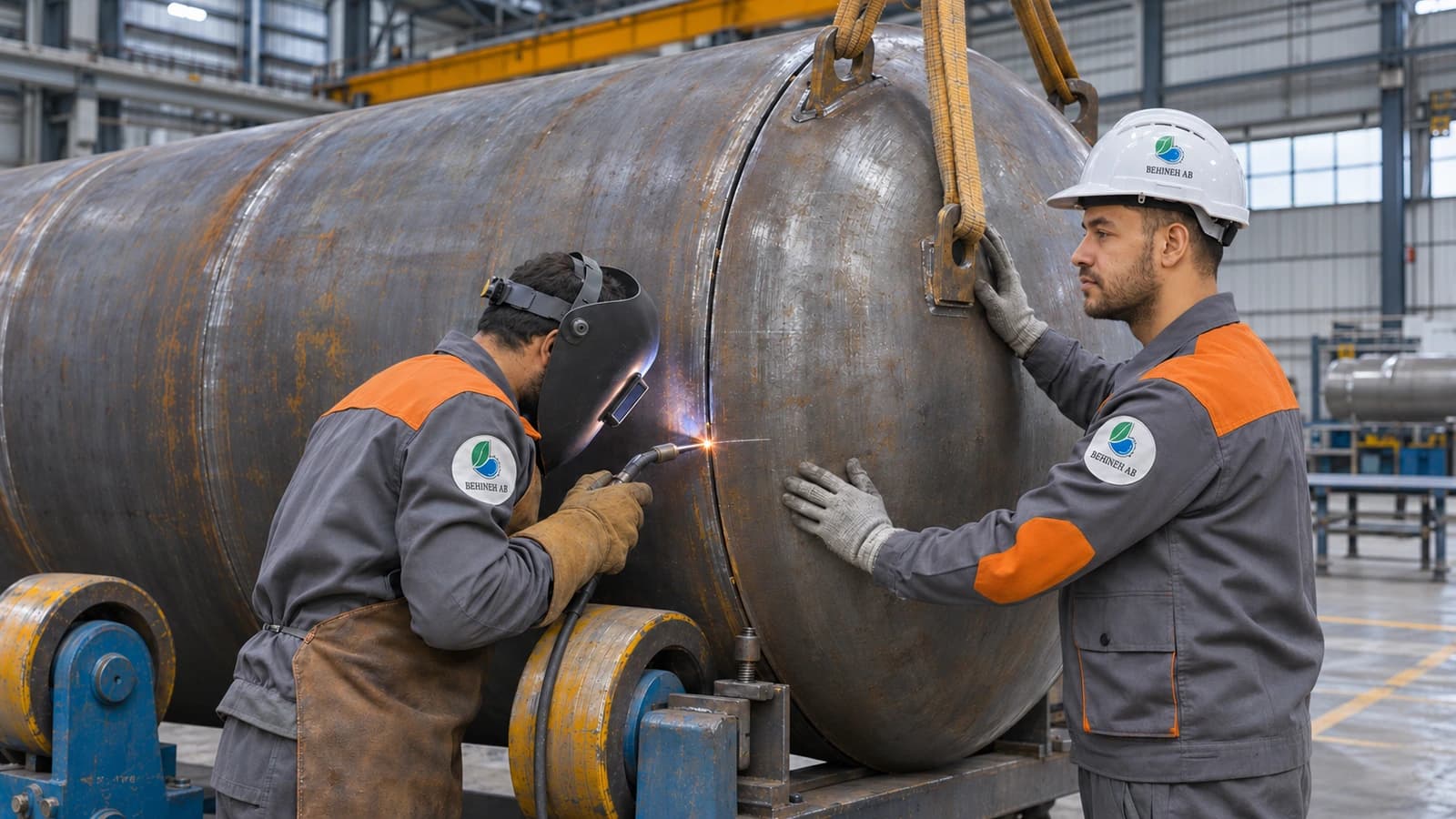
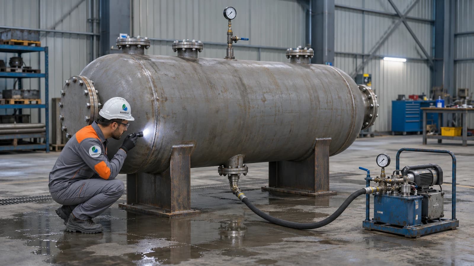
Design and fabrication of
refinery tanks from crude oil to finished product!
From crude oil tanks to finished products, each with its own requirements
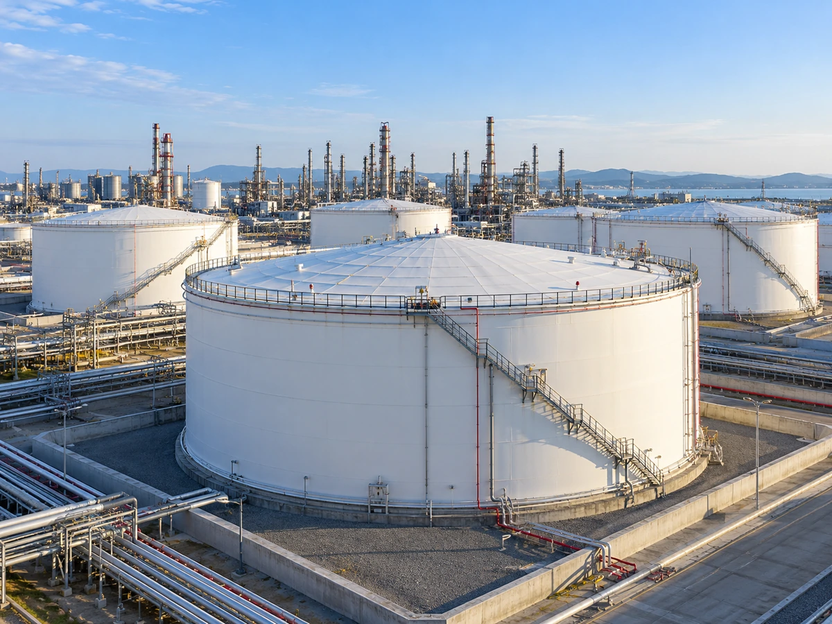
Refinery tanks are not simply one kind of large tank; depending on their place in the refining process there are three broad groups: very large crude oil feed tanks, intermediate tanks for semi-processed products between operating units, and finished product tanks for gasoline, gas oil and other products ready for distribution.
1. Introduction
Refinery tanks are the backbone of fluid storage and transfer in crude oil refining, petrochemical and gas units. They not only store raw materials, intermediate products and finished products, but also act as operational buffer units that manage fluctuations in supply and demand. Correct design, fabrication and operation of this equipment has a direct effect on safety, environmental protection, production continuity and the economic return of the whole plant.
A modern refinery stores a wide range of fluids with different physical and chemical properties, from heavy and sour crude oil to light, volatile products such as gasoline, naphtha and liquefied petroleum gas (LPG). Because of their different vapour pressure, flash point, corrosivity and toxicity, each of these fluids imposes its own requirements on the choice of tank type, materials of construction, sealing system and safety equipment.
With the aim of providing a comprehensive technical reference for design engineers, operators and inspectors, this article reviews the types of refinery tanks, the standards governing their design and fabrication, hazardous area classification requirements, fire-fighting and foam systems, corrosion monitoring and specific design points in the oil, gas and refining industry.
The view of Behineh Ab Engineering
Our approach to refinery tank design is based on integrating three pillars: "inherent safety", "full compliance with international standards" and "long service life through corrosion management".
Design pressure ranges
The choice of design standard depends on the operating pressure; the three common ranges for refinery tanks:
Knowing the pressure and geometry classification is a prerequisite for choosing the design standard; an atmospheric tank is covered by API 650, low pressure by API 620, and pressures above 15 psi by ASME Section VIII.
2. General classification of refinery tanks
Refinery tanks can be classified by various criteria. The most common are operating pressure, geometry, process function and the type of fluid stored. Knowing this classification is a prerequisite for choosing the right design standard.
Three main groups by design pressure range:
| Group | Design pressure range | Typical use | Common standard |
|---|---|---|---|
| Atmospheric tanks | Near atmospheric pressure (up to 0.5 psi) | Storage of crude oil and heavy products | API 650 |
| Low-pressure tanks | 0.5 to about 15 psi | Storage of semi-volatile products | API 620 |
| Pressure vessels | Above 15 psi | Ammonia, liquefied gases, LPG, etc. | ASME Sec. VIII |
The tank geometry depends on volume, pressure and fluid type:
The most common form for atmospheric storage of crude oil and products.
For storing medium volumes of liquefied gases under pressure.
For storing large volumes of liquefied gases under pressure, thanks to the uniform stress distribution.
To reduce evaporation losses of volatile products.
For low-volatility products or materials that need inert gas blanketing.
4. Standards governing design and fabrication
The choice of design standard depends on the operating pressure, fluid type and tank geometry. Three main standards govern refinery tanks:
Use: atmospheric storage tanks (pressure close to atmospheric) with a fixed or floating roof. Scope: design of the shell, bottom, roof and nozzles, and welding and inspection requirements. Important annexes: Annex E (seismic design), Annex F (low internal pressure), Annexes H and C (internal/external floating roofs).
Use: storage tanks with a design pressure up to about 15 psi and low temperatures (such as cryogenic storage). Scope: more complex geometries such as low-pressure domed and spherical tanks.
Use: all vessels with a design pressure above 15 psi, including LPG spheres, separators and drums. Division 1: design rules based on conservative formulas; the most common in refining. Division 2: alternative rules with more detailed stress analysis for higher pressures.
| Standard | Subject |
|---|---|
| API 653 | Inspection, repair, alteration and reconstruction of storage tanks |
| API 2000 | Tank breathing, pressure and vacuum venting |
| API 2350 | Overfill protection |
| NFPA 30 | Flammable and combustible liquids code |
| NFPA 58 | Liquefied petroleum gas (LPG) code |
| ASME B31.3 | Process piping connected to tanks |
| API RP 651 | Cathodic protection of storage tanks |
| API RP 652 | Internal bottom lining of storage tanks |
7. Corrosion monitoring and control
Corrosion is the main cause of shortened life and loss of mechanical integrity in refinery tanks. Corrosion mechanisms in a refinery are varied and appear depending on the fluid type, temperature and impurities.
| Mechanism | Typical location | Cause |
|---|---|---|
| Uniform corrosion | Internal and external shell surfaces | Moisture and oxygen |
| Pitting corrosion | Tank bottom, settled water layer | Chloride and bacteria (MIC) |
| Corrosion under insulation (CUI) | Under the insulation of hot lines and tanks | Moisture ingress |
| Sour corrosion (H₂S/CO₂) | Sour crude oil tanks | Acid gases |
| Stress corrosion cracking (SCC) | Ammonia and amine tanks | Stress + corrosive environment |
Common methods for monitoring integrity and thickness:
Periodic thickness measurement by ultrasonic testing.
Corrosion coupons, electrical resistance (ER) probes and linear polarisation resistance (LPR) probes.
Online monitoring and thickness mapping with permanently installed sensors.
Risk-based inspection to API 580/581 to prioritise inspection.
Testing the tank bottom by magnetic flux leakage (MFL) during major overhauls.
Preventive measures to extend tank life:
Cathodic protection of the external tank bottom (impressed current or sacrificial anode) to API RP 651.
Internal coating and lining of the bottom and shell to API RP 652.
Injection of corrosion inhibitors in associated water systems.
Managing settled water and draining it regularly to prevent pitting corrosion and MIC.
Correct insulation and sealing to control corrosion under insulation (CUI).
9. Conclusion
Refinery tanks cover a diverse range of equipment with various applications and design requirements, from large atmospheric crude oil tanks to pressurised LPG spheres and process separators. Choosing the right design standard (API 650, API 620 or ASME Section VIII), accurately classifying hazardous areas, comprehensive design of fire-fighting and foam systems, and implementing a coherent corrosion monitoring and control programme are the four main pillars that guarantee the safety and continuous operation of these tanks.
Relying on up-to-date technical knowledge and command of international standards, Behineh Ab Engineering is ready to provide consulting, design, inspection and optimisation services for refinery tanks to suit the needs of clients in the oil, gas and refining industry.
Technical specifications
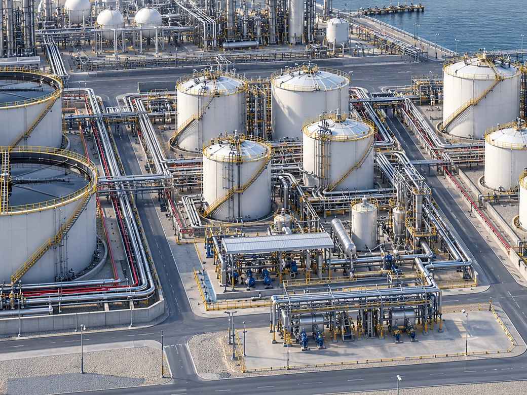
The three main groups of tanks in a refinery
Crude oil tanks are usually the largest components of a refinery and provide the initial feed storage for the refining units. Intermediate tanks move and store semi-processed products between units (such as the distillation unit and the cracking unit). Finished product tanks hold products ready for distribution, such as gasoline and gas oil.
API 650 and API 653 requirements
API 650 is the reference standard for the design and fabrication of welded steel atmospheric tanks and covers shell thickness and the design of the bottom, the roof and the wind girder. API 653, however, is for tanks that have already been built and commissioned, and it governs their inspection, repair, change of service or retirement.
Periodic inspection of refinery tanks to API 653 usually includes measuring bottom and shell thickness, inspecting the welds and assessing the foundation so that settlement or early corrosion is detected.
Special tanks: LNG and high-pressure vessels
Besides the three main groups, some refineries need more specialised tanks: LNG tanks for storing liquefied natural gas at very low temperature, and pressure vessels that in some applications are designed for up to 3000 psi. These are usually built separately from ordinary atmospheric tanks and to different design rules.
A common safety point for all these tanks is the use of anti-slip materials on the stairs and narrow walkways around the tank; a point that is often overlooked in refinery safety inspections.
Tank layout and safety distances (tank farm)
The distance between refinery tanks is not chosen at random; fire safety standards set the minimum distance based on tank diameter, product type and whether there is a bund wall, so that if one tank catches fire the chance of it spreading to neighbouring tanks is kept to a minimum.
A correct layout must also allow for access routes for fire-fighting equipment and the emergency evacuation of personnel.
Applications and industries
Photo gallery
Refinery tank gallery
Frequently asked questions
Request a quote
Refinery tanks
Enter the pressure, temperature and fluid; our engineers send a technical proposal and price within 24 working hours.
- Written technical reply with a proposed concept drawing
- Site visit in Tehran and surroundings
- 24-month warranty on fabrication and welding